

What do you do if you are writing a program to monitor an electric vehicle charger, but the charger just sits there doing nothing, waiting for a vehicle to be plugged in? You create an electric vehicle, of course! Only, it doesn’t need to drive around, or be particularly big. Indeed, it doesn’t even actually have to charge anything! Just as long as it obeys the SAE 1772 electric vehicle charging standard, it can pretend to do everything else.
This device has 240VAC wires, so needed to be housed in an enclosure for safety—I chose a Jiffy™ box. Now, you know what that means: drilling and filing the lid to accommodate the controls, and a rats’ nest of cabling to get them integrated together. Only, no!
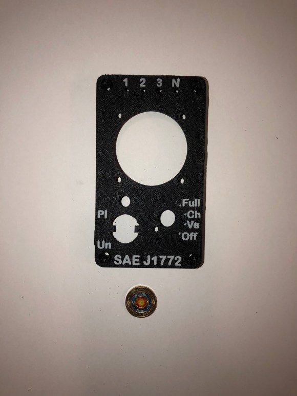
In the first place, I was able to design and 3D print the lid-minus-control-voids (see ThingiVerse) – and also add labels at the same time:
And in the second place, OSH Park’s Flex PCB could provide sufficient accommodation to meet the interconnects:

The whole project has been published in DIYode magazine, an Australian electronics enthusiast’s journal for just this kind of project.
